cnc machining diagram The first sections of the manual take you through the very basics of what a CNC Mill is and what operations it can do, the basics of how the machine works, what G - Code is, the different . Choosing The Right Size Pulls For Your Cabinets: Standard size cabinet pulls can range between 1 inch for small bar and finger pulls and go up to 20+ inches for appliance pulls.
0 · parts made by cnc machine
1 · main parts of cnc machine
2 · cnc machining process flow chart
3 · cnc machine labelled diagram
4 · cnc machine drawing pdf
5 · block diagram of nc machine
6 · block diagram of cnc machine
7 · basic elements of cnc machine
To help you out, we’ve compiled a list of five common household metals and where to find them. We even ranked them by their scrap yard value to help you prioritize your efforts! 1. Copper is often the go-to metal for seasoned scrappers because it consistently gets the best prices at .
This section aims to provide an overview of the various components found in CNC machines. While certain parts such as the control . This guide delves into the basics of machining drawings, their importance, and the essential elements of a CNC machining drawing. You will also learn why you need to prepare a technical drawing when sourcing parts .Make the most of CNC machining by optimizing your design and making the right material choices. Read these 14 design tips to help you reduce CNC-machining costs and create the .The first sections of the manual take you through the very basics of what a CNC Mill is and what operations it can do, the basics of how the machine works, what G - Code is, the different .
CNC machining is a widely used manufacturing technique that involves the use of computer-controlled machines to shape and fabricate various materials. From metal to plastics, CNC .Part 1. The basics. What is CNC? What types of machines are there? Which are their key benefits & limitations? Begin part 1. Part 2. Design for CNC machining. In less than 15 minutes, you will learn how to design parts optimized for CNC .
Precision machining, particularly CNC (computer numerical control) machining, is vitally important in today’s economy, specifically for industries needing parts with unparalleled accuracy and complexity.A CNC machine diagram works by providing a detailed visual representation of the internal make-up of a CNC machine. This consists of mapping out the interaction between various parts,including the motors,drive system,controller,and tooling. These schematic representations prove valuable in troubleshooting technical glitches,servicing routines .

Rotary Table Milling Machine Diagram and Main Parts. The main components of rotary mills typically have these parts, and some of the components can be included or not depending on the product manufacturer or applications. . – Stepper motor (for CNC versions): To allow for automated rotation. – Dividing plates (optional): For precise .Diagram of a CNC Machine. Elements of CNC Machines. The followings are the elements of CNC machines: 1. Program. This is the computer input that is done with a keyboard when trying to tell the machine to perform a functional control code. This control code is of two sets; G-codes and M-codes. M-codes are miscellaneous machine commands that do . Your beginner-friendly resource to understanding CNC! A complete manual to understanding the fundamentals, machinery, software, tools, and materials of CNC; Hands-on projects that incorporate various concepts and techniques in digital wood joinery and 2-1/2 D carving; Easy-to-understand text is clear, approachable, and applies to a wide range of .
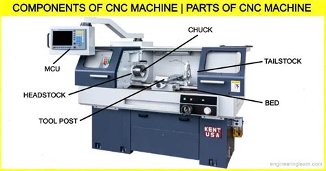
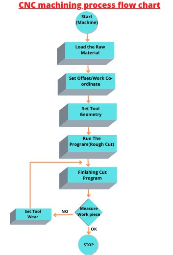
learn CNC machining process flow chart-CNC machining process flow diagram. CNC machining process flow chart. Flow chart Explanation step by step-Steps of Flow chart: Explanation: Start: Start the Machine: Load the raw material: Load the raw material on machine/Hold by chuck. Set offset/work co-ordinate: CNC Machining . Fanuc OT Ladder Diagram F Signal Diagnosing. Thread starter MaintenanceMan! Start date Apr 28, 2021; Replies 3 Views 2,792 M. MaintenanceMan! . I believe that I've got it narrowed down to the Reset bit in the ladder diagram being stuck on. Its not the button itself, the bit in the ladder diagram that is stuck on is F149.1. . The descriptions of machine elements (headstock, chuck, lathe bed, etc.) are generic. Nomenclature and layout may vary between manufacturers. The lathe machine diagram for your tool will give you the manufacturer's version of the naming. Best Upgrade for CNC Lathe Machine Parts. The best upgrade for CNC lathe machine parts varies depending on .
Here, we delve deeper into each CNC machine part, providing detailed explanations, diagrams, and references to related resources. We highlight the role of each part in enhancing precision, speed, durability, and overall performance. Additionally, we provide insights into common maintenance practices and troubleshooting tips, ensuring your CNC .A CNC machine line diagram is a graphical representation of a CNC machine's electrical and mechanical components, including the drive, motor, and other elements. These diagrams are critical because they enable users to troubleshoot problems and .

The 5 axis cnc machine diagram begins with the axis system. This machine operates along five axes: X, Y, Z, A, and B. The X, Y, and Z axes represent the linear movements, while the A and B axes are responsible for rotational movements. This combination allows the machine to achieve complex shapes and angles with ease. 2. The X, Y, and Z Axes
A ladder diagram is an electrical schematic drawn according to a convention that has the two ladder “rails” being power supply lines and the “rungs” of the ladder between circuitry that passes between the two lines. . The components used to convert a manual machine to a CNC machine are all motion control components. Motor Driver: See .CNC Machining is a subtractive manufacturing technology, where material is removed from a solid block, or workpiece, using various CNC machining equipment such as milling machines, lathes, and grinders. This process is known for its high precision and versatility in creating a wide range of materials, including metal, plastic, wood, foam, and . A CNC machine tool always has a sliding table and a spindle to control the position and speed. The table of the machine is controlled in the X and Y-axis direction and the spindle is controlled in the Z-axis direction. Driving System. The driving system of a CNC machine includes an amplifier circuit, drive motors, and ball lead screws.
parts made by cnc machine
In this article, we will explore the main parts of a CNC machine and explain the CNC block diagram in simple terms. 7 Key Components of a CNC Machine 1. Machine Control Unit (MCU) The Machine Control Unit is the brain of the CNC machine. It reads the G-code (the programming language for CNC) and converts it into electrical signals that control .
A modern CNC lathe machine diagram, courtesy of CNC Masters . Today’s multi-axis CNC machining centers can blur the lines between CNC lathes and CNC milling machines, but they are two separate and distinct .A CNC machine circuit diagram typically involves four main components:power supplies,drivers,control unit,and motors. The power supply facilitates the conversion of main power into a form suitable for the machine's operation,while drivers control the motors that move the machine parts. The control unit holds the computer that sends commands to . Computer Numerical Control (CNC Machine) CNC machines emerged after NC machines to overcome their limitations. Instead of using a tape reader, CNC machines utilise a computer-generated file containing G-Codes .
A CNC machine wiring diagram is a documented blueprint detailing the electrical connections necessary to power a CNC machine. The diagram typically includes a connection point map with detailed diagrams of the different cables and their connections to the control system. It also provides information about the physical placement of components .
In this complete guide to designing for CNC machining, we've compiled basic & advanced design practices and tips to help you achieve the best results for your custom parts. 20% off your first order. Save up to ,000/€1,000. Ends 30 Nov 2024. Get a quote. Help center. EN.To request a quote for custom CNC parts on the Protolabs Network platform, you only need to supply a 3D CAD file. Modern CNC machining systems can interpret the geometry of a part directly from CAD, which means that additional documentation, such as technical drawings, isn’t always required.. However, while technical drawings are not necessary to request a quote for . The goal of all this, is the creating of Stability Lobe Diagrams of our milling machine of different tools. I have no idea as I said how to produce them. My question is if is there anyone to tell me the procedure (the steps to follow) after the measurements (experimental and analytical way). . CNC Machining. ABOUT PRACTICAL MACHINIST. With .Download scientific diagram | Schematic of a CNC tool from publication: Understanding Energy Consumption in a Machine Tool through Energy Mapping | Understanding where energy is consumed in a .
An ATC can either be mounted on the column or separately from the machine and the G-code from the CNC program activates the CNC tool changer to automatically replace the tool for further machining. However, CNC tool changers or ATCs can be expensive and are only suitable for industrial applications where high productivity is of utmost importance.This document describes the key components of a CNC machine. It discusses 13 parts, including the machine control unit that interprets G-code and controls the machine, the driving system that moves tools along axes using motors and screws, and the feedback system that verifies tool positions. It also explains machine-specific components like the headstock and tailstock on .
There is plenty more to learn about CNC machining in our Knowledge Base - a collection of technical articles on all manufacturing technologies, written by manufacturing experts and curated by Protolabs Network. Here is a selection of our most popular articles on CNC machining: Reducing the cost of CNC machined parts →; 3D Printing VS. CNC .
4. Understanding CNC Machine Schematic Diagrams\ a. Block Diagram\ b. Electrical Diagram\ c. Signal Flow Diagram . 5. How CNC Machine Schematic Diagrams Work\ a. Power Flow\ b. Signal Flow . 6. Troubleshooting CNC Machine Schematic Diagrams\ a. Common Issues\ b. Testing and Maintenance . 7. Best Practices for CNC Machine Schematic Diagrams\ a. As a computer numerical control manufacturing process, CNC machining has revolutionized the production of complex parts and components. It is crucial to have a well-defined process flow chart .
main parts of cnc machine

I bought the Ring Floodlight Cam and went to install it, only to realize the current junction box is rectangular. I understand I need a new cicular junction box. What do I buy?
cnc machining diagram|block diagram of cnc machine